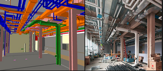
A good example of an installation that typically requires shop drawing preparation and submittals would be galvanized steel duct-work distribution for a forced air system, which is a sub-component of many heating-ventilation-air-conditioning (HVAC) designs. Such a system must be properly dimensioned, detailed, and depicted not only in itself, but in relation to adjoining structure or program – typically between the floor or deck above and the finished dropped ceiling below.
First, the fabricator will generate schematics that represent the general design concept, are useful to verify constructability, and impart a general sense of material and labor needed to perform the work. These are typically based on the design drawings and pre-construction site visit. These schematics may be run by the engineer for his opinion, however, they are not always a required submittal (check the specification submittal requirements for each trade).
Subsequent to preparing schematics, the contractor may pre-submit his shop drawings for approval to the design team based on his schematics, which will have incorporated the design drawings. These drawings will show expected routing and rough dimensions of the duct system, including equipment, such as air-handlers, fan-coil units, etc. Despite claims to the contrary, ductwork can seldom be fabricated according to such preliminary submittals.
Although initial or preliminary shop drawings may not as yet be fully dimensioned, the engineer may issue approval pending final details. The reason partially dimensioned or incomplete shop drawings are often issued is to save time, as HVAC systems are usually in the critical-path of the schedule. For example, the fabricator may order his material while he awaits field dimensioning. In either case, a set of as-builts is typically issued at the completion of the work to represent the actual installation.
While duct shop drawings may be submitted for approval before dimensions can be finalized in the field, many details need to be refined before fabrication can start, such as:
- Top and bottom of duct dimensions from finished floor – especially where duct is stacked or intersects
- Lengths of ductwork, especially where duct sizes change or transition
- Direct take-offs from equipment supplies and returns
- Offsets from intersecting elements, and adjacent program and framing, some of which may not be in place
- Dimensioning of turning radii
- Final dimensions, including fittings and insulation that make clearances changeable
Naturally, the engineer and architect will eventually want to know this information; however, they may give partial approval to shop drawings pending final dimensions, in order to allow the fabricator to save time, or resubmit.
Another reason why it’s risky and likely ill-conceived for the contractor to fabricate before major framing elements are in place is because there is always a strong likelihood that not everything will be constructed as planned, or unforeseen or hidden conditions necessitate a change of plan. If material needs to be refabricated because it was not properly coordinated or dimensioned the contractor will be liable for the costs. This is why smart fabricators do not manufacture until they can guarantee “hold” dimensions. As ductwork is fabricated off-site, there is no way to correct mistakes in the field.
Next, we will discuss the integration of the ductwork into the rest of the program in
Part 3: MEP coordination, BIM & CAD: how do Shop Drawings fit in?
go back to
Part 1: Taking the Mystery out of Construction Shop Drawings


