What are construction shop drawings? There is no simple answer. Ask more than one person and you’ll never get the same response. Depending on whom you ask – owner, architect, contractor, or manufacturer, you may hear vastly different opinions, including arguments as to what constitutes proper shop drawings as opposed to – well, something else. This lack of clarity facilitates a great degree of complication for the industry.
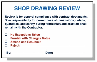
Shop drawings are a standard tool for mechanical/electrical/plumbing (MEP) architectural millwork and metal work, reinforcing steel, structural steel, and many other trades. Shop drawings must typically be accompanied by additional information, such as product and technical data, and specifications. Each individual project requires a set of submittals unique to that project’s designs and field conditions. Single-family, or small home construction, for example, may forgo the process altogether, whereas large office buildings will require a much more stringent planning and oversight process.
In plain terms, shop drawings are meant to show a specific level of fabrication and installation detail for a given trade that are typically not represented, or are not refined, in the design drawings. Of course, design drawings can vary in terms of level of detail, and many are more sophisticated than what often passes for shop drawings. Conversely, many contractors waste valuable time issuing under-developed shop drawings that must continually be resubmitted and re-reviewed.
One common misconception regarding shop drawings is that they are suitable for fabrication purposes. While in some cases, such as where there are high tolerances, basic shop drawings can be used for fabrication; however, they generally must be taken to the next level; which is field dimensioning or detailing. In Part 2, let’s look at how a sample building forced air duct system may be detailed and fabricated.
