Once the project begins to take shape, a detailer, or sketcher, can visit the site with his preliminary shop drawings in hand to survey and measure the site. He will then add dimensions to his shop drawings which will then become fabrication drawings that the manufacturer and installer will later use.
There will be certain restrictions he will want to pay particular attention to, for example, where interior space is at a premium, designers will want to see the duct high and tight without encroaching on the space below, or lowering the ceiling height. The tighter the space above the ceiling, the more complex will be MEP coordination, which must also integrate the electrical and lighting plan, and plumbing and fire suppression plan.
As ductwork takes up the most space above the ceiling, and has the least wiggle-room, duct mains and larger branches are typically detailed first, and the balance of program around it. The duct work shop drawings kick-off the coordination process. The mechanic, or HVAC contractor, is therefore in the best position to take the lead, and is often the designated captain of the effort. Once the basic duct plan is developed, the electricians, plumbers, fitters, and other trades, can integrate their plans using the duct shop drawings as backgrounds.
It is generally not recommended that electrical and plumbing trades begin their shop drawings in earnest until the ductwork system is configured. In this way, they can ascertain where conflicts may be expected, and best plan their own routing. Often a translucent Mylar sheet is used as an overlay for this process, as sketches and mistakes can be easily wiped away. These MEP coordination drawings are part of the contractors’ means-and-methods, i.e., they typically are not subject to design team approval. Nonetheless, MEP coordination is often not implemented when it needs to be. Omitting the MEP coordination stage can lead to program conflict, tear-out/re-do work, and delays. This is not uncommon for off-radar projects, where no one may really be paying attention
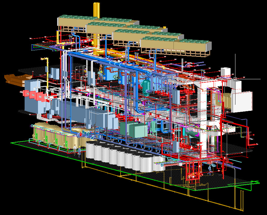
BIM generated design drawings can be used to facilitate a high level of shop drawings that only need clarification and confirmation to real-time or actual conditions by leap-frogging cumbersome traditional manual survey practices and minimizing the likelihood of error. BIM software features pre-build three-dimensional views of the planned infrastructure that was virtually unheard of before such modeling capabilities began to become mainstreamed. In other words, MEP coordination can be substantially developed even before the project breaks ground.
BIM is part of the design modeling process that is used for very large projects, or rather, those projects that involve players who can afford the implementation and training of costly BIM systems. BIM can be a panacea for MEP and general coordination, but as yet it lacks industry wide participation. In any case, field surveys are typically done manually, and the information later incorporated digitally.
For the rest of the pack; especially subcontractors, they must rely on CAD project drawings, which they use as backgrounds for third-party drafting software, or simply overlay their Mylars on these backgrounds. This latter method is most useful for coordination drawings, such as busy ceiling areas that may have complicated integration of duct work, light fixtures, plumbing pipe, and other program. In any case, it is standard practice for a sketcher to make a site visit to verify field conditions on paper, and scope out conflicts, and then later plot his sketches with his mechanical drawing software. For a BIM project, a detailer’s dwg (AutoCAD) files can be uploaded and integrated into the BIM system, to complete the coordination effort.
So how do you know when you have the real thing in-hand?
Read ahead to …
NEXT POST – Part 4: Shop Drawings or Sketches: What’s the Real Deal?
PREVIOUS POST – Part 2: Example of Shop Drawing & Detailing
